
Neal Chance Bolt Together Converter
Assembly Instructions
Bolt Torque Specifications
- Converter to Flexplate 7/16-20 bolts: 40-50 ft. lbs. Locknut Highly Recommended
- Bolt Together 5/16-24 bolts (Steel & Titanium): 17-20 ft. lbs. Use small amount of anti-seize on these.
- Full Billet Drive Hub Bolts: 15 ft. lbs.Recheck these when you have the converter out.
Bolt Circle Sizes
| Converter Dia. | Bolt Circle | Thread Size |
|---|---|---|
| 8″ steel | 3 on 10.750″ bc | 7/16-20 |
| 8″ alum | 3 on 10.750″ bc | 7/16-20 |
| 8″ alum | 6 on 10.750″ bc | 7/16-20 |
| 9″ steel | 3 on 10.750″ bc | 7/16-20 |
| 9″ alum | 6 on 10.750″ bc | 7/16-20 |
| 10″ steel | 3 on 10.750″ bc | 7/16-20 |
| 10″ steel | 6 on 10.750″ bc | 7/16-20 |
| 10″ alum | 6 on 10.750″ bc | 7/16-20 |
| 10″ Big Option | 6 on 11.500″ bc | 7/16-20 |
| 10″ Multi Option | 3 on 10.750″ 3 on 11.500″ bc |
7/16-20 |
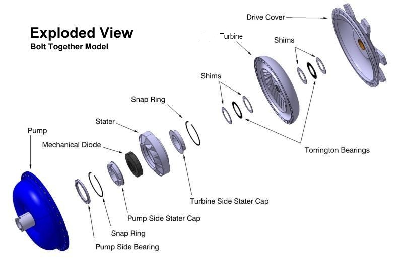
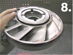
Converter Layout
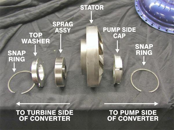
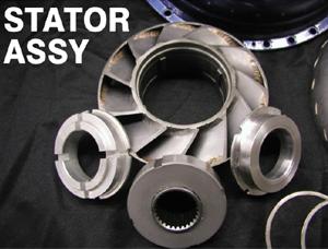
Stator Assembly
Mechanical Diode Instructions
Neal Chance uses the following style Mechanical Diodes in converter assemblies. The NCRC Regular Diode has 5 Stuts, our Monster Diodes are the ones with 10 Struts. Here is a list of the relevant NCRC Freshen Kit Part Numbers for reference:
| PN# GM-MD | Chevy Style 5 Strut Diode Kit |
| PN# GM-MD12 | Chevy Style 10 Strut Diode Kit |
| PN# FD-MD | Ford Style 5 Strut Diode Kit |
| PN# FD-MD12 | Ford Style 10 Strut Diode Kit |
| PN# FMX-MD12 | 10 Strut for 1 3/16″ Input Shaft Transmissions |
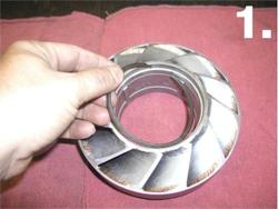
Assembly of Mechanical Diode
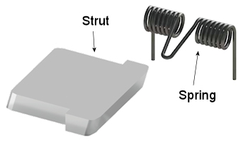
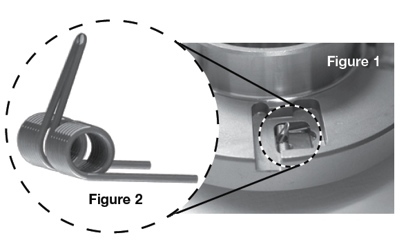
- Place the core on a suitable work area with the spring and strut cavities facing up. The spring and strut cavities have two levels, see Figure 1. Note: Proper positioning of the spring and strut are critical for correctly assembling the unit.
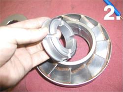
 Orient the spring as shown in Figure 2. When installed correctly, the spring will look like the one shown in Figure 1.
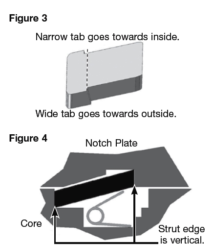
- The strut is basically square-shaped with two tabs. Note the two tabs are different widths (Figure 3). Installing the small and large tab in the matching small and large cavities positions the strut for correct operation. Install the strut with the smaller tab inboard on the hub and the larger tab outboard on the hub. Note: The load-bearing edges of the strut are angled and should appear as shown in Figure 4 when installed.
- Place the notch plate with the spiral ring groove (ring groove facing down) onto the core. You will begin to feel spring tension as the plate comes into contact with the struts. Continue pushing the plate down until the springs are fully compressed. Hold the two parts firmly together and turn the assembly over to expose the spiral ring groove. If the ring groove is not visible, the springs and struts are not installed correctly.
- Continue holding the parts together and install the spiral retaining ring.
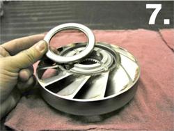
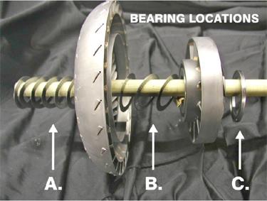
Bearing Layout and Shims
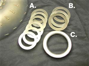
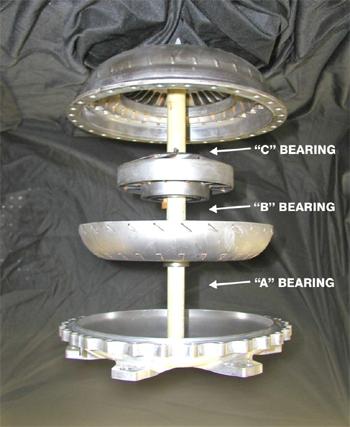
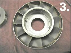
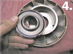
In the converter there are a total of 3 bearings. They include 1 self enclosed bearing on the pump side of the stator (C) and 2 ea. Torrington style bearings, 1 ea. between the stator and the turbine, and 1 ea. between the turbine and drive cover.
NOTE: that on the Torrington style bearing a race is mandatory on both sides of the bearing and any extra races are used as shims.
IMPORTANT: An “O” ring is required to seal the pump and drive cover. NEVER reuse an “O” ring or substitute another product in its place. Failure to do so may result in damage to the product with serious results.
Torque specs on the bolts around the converter are 17-20 ft. lbs. Do Not Over Torque!! Make sure and use a star pattern for the first 8 bolts tightened.
Making Adjustments to Stall Speed
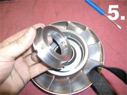
To shim the converter to “full loose” move the extra shims (3 maximum) to the area between the turbine and stator.
NOTE: that the shims must remain the same size and you may have to order shims to complete this operation. If your converter has different size races then keep in mind you must remove from one side and then add to the other keeping the same number of shims as you started with.
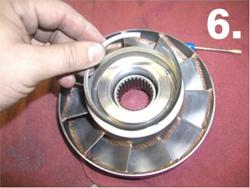
To shim the converter “full tight” move all extra shims to the area between the turbine and drive cover. NOTE that the shims must remain the same size and you may have to order shims to complete this operation. If your converter has different size races then keep in mind you must remove from one side and then add to the other keeping the same number of shims as you started with.
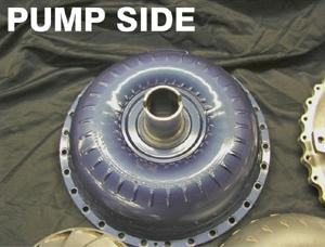
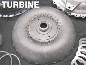
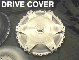
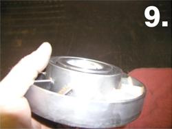
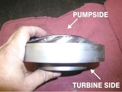
Component Names
When discussing your torque converter with NCRC, or with other racers, it is helpful to have a clear understanding of what the different component parts are called.